How to Read Data From a Serial Port
What a serial port actually is, how baud rate and 8N1 framing work, where the port shows up on Windows, macOS and Linux, and how to read the data.

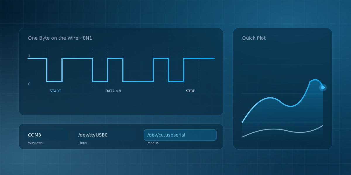
Reading a serial port means three things: opening the device your operating system exposes, setting the baud rate to match the sender, and receiving the stream of bytes that arrives. If you have wired up an Arduino, an ESP32, a GPS module, or almost any microcontroller, you have done all three already, probably without thinking much about it. It is worth understanding, because a few minutes on the basics will save you hours of chasing "garbage on the screen" later.
What a serial port really is
"Serial port" usually means a UART: a Universal Asynchronous Receiver-Transmitter. It is the small piece of hardware that turns a byte into a sequence of bits on a single wire, and turns bits back into bytes at the other end. A UART is a peripheral, not a protocol. The protocol it speaks is plain asynchronous serial, which is what a datasheet means when it says a chip "speaks serial at 115200 8N1".
The word asynchronous is the important one. There is no shared clock line between the two ends. Instead, both sides agree in advance on how fast the bits arrive, and the receiver re-synchronizes at the start of every byte.
The frame, and 8N1
Every byte travels inside a small fixed-shape frame:
- The line sits idle (logic high) when nothing is being sent.
- A single start bit pulls it low. That falling edge is the receiver's cue to start sampling.
- The data bits follow, least-significant bit first. Eight bits is by far the most common width.
- An optional parity bit can catch single-bit errors.
- One or more stop bits return the line high before the next byte.
The usual configuration is written 8N1: 8 data bits, No parity, 1 stop bit. With the start and stop bits, that is ten line-bits per byte, so the raw efficiency is 80 percent. Most modern devices leave parity off, because USB and short cables rarely flip bits and any error checking that matters lives in the application layer.
flowchart LR
    subgraph frame["One 8N1 frame"]
        direction LR
        s["Start bit<br/>line pulled low"] --> d["8 data bits<br/>least-significant bit first"] --> p["Stop bit<br/>line back to idle high"]
    end
Baud rate: the one setting people get wrong
Baud rate is how many bits per second travel on the line. At 9600 baud each bit lasts about 104 microseconds; at 115200 it lasts about 8.7. Common rates are 9600, 19200, 38400, 57600, 115200, 230400 and up.
Both ends must use the same rate. UARTs tolerate a small clock mismatch (the error accumulated across one byte has to stay under half a bit, which works out to a few percent), but if the configured rates actually differ, you get nonsense or nothing at all. A useful tell: a wrong rate produces consistent garbage, the same wrong bytes every time you send the same data, rather than a mix of correct and random characters. If instead most of the text is right with the odd mangled character, suspect noise or wiring before you touch the baud rate.
Why high baud rates fail on long wires
There is a second failure mode that has nothing to do with configuration, and it appears exactly when you raise the rate to get more data through. A UART pin drives the cable directly, and the cable pushes back: every pair of wires has capacitance, on the order of 50 to 100 pF per meter for ordinary hookup wire or ribbon cable, and the transmitter must charge and discharge that capacitance through its own output resistance on every edge. The result is an RC low-pass filter you did not order. The logic edges leave the pin square and arrive rounded.
Whether that matters is arithmetic. At 9600 baud a bit lasts 104 microseconds, so an edge that takes two microseconds to settle is invisible. At 1 Mbaud the entire bit is one microsecond, and the same lazy edge eats most of the bit's budget; the receiver, sampling mid-bit, reads the previous bit's leftovers. This is why wiring that is rock solid at 115200 turns to garbage at 921600 with nothing broken: the wire is a filter, and you moved the signal into its stopband. Noise stacks on top. A 3.3 V signal measured against a ground wire that also carries a motor's return current can watch the logic thresholds walk straight through its data.
Industry ran into this decades ago and the answers are still on the shelf. RS-232 specified driver swings and slew rates precisely to make cable behavior predictable, and its capacitance budget works out to roughly fifteen meters at modest rates. For longer runs, RS-422 and RS-485 send each bit as a voltage difference between two twisted wires, so interference hits both conductors equally and cancels at the receiver; the same asynchronous byte framing described above survives a kilometer of factory cable that way. The practical bench rule falls out of the physics: keep logic-level UART wires short and slow, and when you need long or fast, change the electrical layer, not just the number.
Where the port appears
The same physical adapter shows up under a different name on each operating system:
- Windows: a
COMport, such asCOM3. - Linux: a device file, usually
/dev/ttyUSB0(for a USB-to-serial chip) or/dev/ttyACM0(for a board with native USB). - macOS:
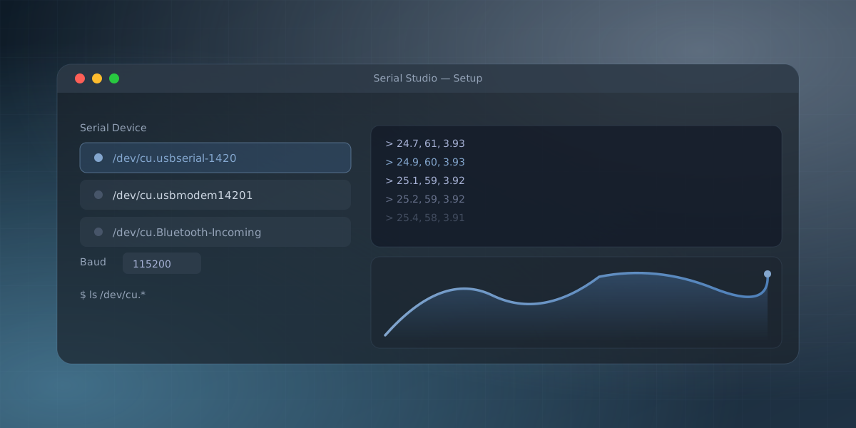
/dev/cu.usbserial-XXXXfor adapters based on FTDI or CP210x chips, or/dev/cu.usbmodemXXXXfor boards with native USB. Using a serial monitor on macOS covers the Mac-specific details.
Whatever the name, opening it gives you a stream of bytes. Nothing more. A serial port has no idea whether those bytes are text, numbers, or a binary packet. That meaning is up to you.
The buffers between the pin and your program
The stream feels like a wire, but between the UART pin and your program sit three layers of buffering, and each one can quietly reshape the data.
The first is on the chip itself. A UART's receive FIFO is tiny: the classic 16550 held 16 bytes, and many microcontroller UARTs hold one to four. If the software servicing it is late (interrupts masked, a higher-priority task hogging the CPU), the next byte overwrites the last and the hardware just sets an overrun flag that almost nobody reads. The byte is gone, no error reaches your screen, and every byte after it shifts one position in whatever protocol you were parsing.
The second layer is the USB adapter, and it explains a mystery nearly everyone meets eventually: data that should arrive as a smooth trickle shows up in clumps. USB does not carry bytes as they happen; the adapter accumulates them and ships them in scheduled packets. FTDI chips, for example, hold received bytes until either a packet fills or a latency timer expires, and the timer's default is 16 milliseconds. Stream one sample every millisecond and your "real-time" data arrives as a burst of sixteen samples, sixty times a second. The timer is adjustable (in the port's advanced settings on Windows, via /sys/bus/usb-serial/devices/.../latency_timer on Linux), but the deeper lesson is that arrival time is not measurement time. If timing matters, the device should say when each sample happened, as data in the frame, rather than letting the host guess from when bytes surfaced.
The third layer is the operating system's own receive buffer, kilobytes deep. It absorbs bursts gracefully, but if the reading application stalls long enough, it too fills and drops data silently. The chain's lesson is the same at every link: a serial stream guarantees byte order, not byte timing, and not even delivery when a buffer overruns. Protocols that matter put a frame boundary and a checksum in the data so the receiver can tell.
Hardware flow control: RTS/CTS, and where DTR bites
Two more wires show up on many serial cables besides TX, RX and ground: RTS (Request To Send) and CTS (Clear To Send). They let either side tell the other "pause, my buffer is full" before bytes get dropped, instead of after.
The mechanism is simple. Each end drops its RTS line low when its receive buffer is filling up, and the far end must hold off sending until RTS returns high. CTS is that same signal read from the transmitter's side: it says whether the receiver is currently clear to accept the next byte. Honor it on both ends and the FIFO overrun problem described above mostly disappears, because the sender never outpaces what the receiver can drain.
Most small projects never wire it up, and that is usually fine. A typical USB-to-serial adapter or Arduino-style board only breaks out TX, RX, ground and DTR, so there is often no RTS/CTS pair available even if you wanted one. Reading the port promptly and pacing transmission with a short delay in the firmware accomplishes the same goal in software, without the extra pins. Flow control earns its place on links pushing sustained high throughput into a slow or busy receiver: old-school modems, some GPS receivers under heavy load, or RS-232 gear that genuinely cannot afford to lose a byte.
DTR is a different signal with a different job, and it is worth not confusing the two. It began life as a modem-control line meaning "the computer is ready to talk," but Arduino-compatible boards repurpose it as a reset trigger: opening the port toggles DTR, a small RC circuit turns that toggle into a brief reset pulse, and the bootloader wakes up expecting a new sketch. That is exactly why opening a serial monitor can unexpectedly reboot the board and swallow the first line or two of its output, and why some serial tools ship a "disable DTR" or "no reset" option for precisely this case.
What the bytes usually are
For debugging, most firmware prints human-readable lines of numbers. A sketch that streams a filtered sensor reading might do nothing more than this:
void loop() {
  int value = analogRead(A0);
  Serial.println(value);   // one number per line, at 115200 baud
  delay(10);
}
That is exactly what the Serial Studio pulse-sensor example does with a heart-rate sensor on pin A0. If you send several values, separate them with commas on one line:
Serial.print(temperature);
Serial.print(",");
Serial.println(humidity);
Actually seeing it
To read the port you need a program that opens it at the right baud rate and shows you what arrives. The Arduino IDE has a Serial Monitor for text and a Serial Plotter for a basic graph. They work, but they are minimal.
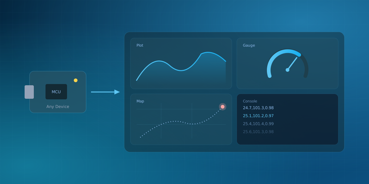
Serial Studio reads the same stream and does two useful things with it. Its console shows the raw text (or hex, if the data is binary), and its Quick Plot mode splits each incoming line on commas and draws every value as a live trace, with no configuration. You pick the port, set the baud rate to match your firmware, and choose Quick Plot (Comma Separated Values) under Frame Parsing. It also records the session to a CSV file you can open later.
Two things that trip people up
- The board resets when you connect. On an Uno or Nano, opening the port toggles the DTR line, which the bootloader reads as "reset". That is normal. If you need to prevent it, disable the DTR signal in the port settings.
- The port opens but nothing arrives. Usually the transmit and receive lines are swapped, or the baud rate is wrong. Check the rate first, since it is the quicker fix.
Once you can see a clean column of numbers, you understand the serial port. Turning those numbers into gauges and plots is what comes next, or if you'd rather follow a full walkthrough first, your first Serial Studio project picks up exactly here. If you're choosing a terminal tool on Windows instead of Serial Studio, the equivalent guide covers COM ports and PuTTY.
Frequently asked questions
What baud rate should I use?
Whatever your firmware sets; the two just have to match. For new code, 115200 is a sensible default: fast enough for most debugging, slow enough for any adapter. One useful exception: boards with native USB (a Leonardo, a Teensy, most modern dev boards) only emulate a serial port, so the configured baud rate is ignored and data moves at USB speed regardless of the number you pick.
Why does my serial port say "busy" or "access denied"?
Something else already has it open. Serial ports are exclusive, so a forgotten serial monitor, a stray screen session, or the Arduino IDE's own console will lock everyone else out. Close the other program. On Linux there is a second cause: your user needs permission for the device, which on most distributions means adding yourself to the dialout group and logging in again.
Can two programs read the same port at once?
Not directly; the first one to open the port owns it. If you genuinely need two readers, one program has to own the hardware and re-publish the data, for example over a local TCP or UDP socket that the second program connects to.
I opened the port and see garbage. Which setting is wrong?
Check the baud rate first, then the data format (nearly everything is 8N1, but not everything). The pattern of the garbage is diagnostic: the same wrong characters every time points to a rate mismatch, while mostly-correct text with occasional corruption points to wiring, noise, or a voltage-level mismatch between a 5 V and a 3.3 V device.
Comments